Different uses of FEA (Finite Element Analysis)
In general, Finite Element Analysis (FEA) is widely used in the stages of design and manufacturing to make decisions that optimize the cost-benefit relationship, allowing for comparison between different approaches and simulating various operating and environmental conditions before the creation of physical prototypes. This approach methodology has led to significant advancements and time and cost savings.
Likewise, FEA is extensively utilized in cases of failure analysis (FA), fitness for service (FFS), and rating, repair, or modification of piping systems, facilities, and equipment. It is also employed in extending the service life by modifying the severity of operating conditions (derating).
Utilization of Finite Element Analysis (FEA) in failure analysis
When investigating a failure, there are imperative questions that need to be addressed. First, from an academic and media perspective, there is a focus on determining what can be done to prevent a recurrence. This is, of course, related to reducing risks, improving operations, evolving in design, etc. To achieve this, it is necessary to determine the failure mode and the factors that contributed to it. Other questions are more related to assigning responsibility: How long has the problem been developing? Was the event unexpected or could it have been detected? Was everything possible, necessary, and legally required done to prevent the accident?
In all cases, the study using Finite Element Analysis (FEA) will have to consider alterations to the original conditions. These alterations to the design conditions can arise from various factors, such as changes in operating conditions (including operational errors), degradation and thickness reduction due to corrosion, modifications in control systems, environmental conditions, soil movements, appearance of wear, cracking, fire damage, crushing or damage by third parties, etc.
It is very rare for failure analysis to directly lead to design issues where all variables have surely been considered and validated through testing and experience. Design issues cannot be claimed in a power generator engine that has been in service for 20 years. The likelihood of addressing design issues in failure analysis increases when incorporating technologies under development.
In all cases, modeling presents different challenges because the aforementioned factors do not produce or adhere to geometric patterns easily reproducible in CAD. It is also necessary to define the level of detail to delve into regarding the defects, striking a balance between obtaining reliable results and computational cost.
Stress analysis or any other type of analysis performed using FEA alone does not solve all the questions raised; it is another element of judgment that complements the overall picture being formed throughout the failure analysis process. In general terms, FEA better defines and distinguishes between what is possible and what is unlikely, and becomes relevant when the rest of the available or generated evidence in the failure analysis does not clearly indicate a single failure mode. Ultimately, the greatest weight of FEA lies in validating or rejecting hypotheses regarding the causes.
Failure Analysis using Finite Element Analysis (FEA) in complex geometries
When the components involved in the failure have complex geometries that deviate from the concepts of pipes, plates, or membranes, or slender bodies with constant sections, the FEA method is (today) the most immediate to identify hot points or sites where higher stress values occur. The determination of these is necessary to predict or justify the occurrence of fatigue initiation and propagation, for example.
Fatigue and Crack Propagation
To address the topic of fatigue, there is enough theoretical and empirical knowledge to fill libraries, and a multitude of publications that are impossible to keep up with today. The theories no longer have proper names and are anonymously crowded within the standards that contain them. However, despite all this, catastrophic failures, which account for 90% of cases, still occur due to fatigue.
Another separate chapter is the use of FEA in crack propagation and the determination of its criticality. The fundamental problem lies in the fact that the discontinuity generated by a crack cannot be addressed using traditional meshing due to the singularity at its tip, and both the growth and criticality depend, among other factors, on the crack size. The objective is to determine the Stress Intensity Factor of the crack with sufficient accuracy.
Several methods have been developed in recent years, including the stress-based method, the displacement-based method, and the line integral or J-integral evaluation. They also incorporate processes to predict crack growth, including the direction of propagation. Methods for evaluating crack growth are generally mesh-dependent and require continuous remeshing as the crack advances. Ways to improve the accuracy and efficiency of modeling, such as the eXtended Finite Element Method (XFEM), have been implemented by commercial software.
Studying the time-dependent mechanisms of damage progression, such as fatigue, corrosion fatigue, or creep, initially allows for the assessment of the remaining life of the equipment. However, it is important to note that calculated propagation rates vary significantly depending on the specific conditions of the environment, materials, and residual stresses. The latter require specific treatments depending on the generation mechanism, such as heat treatment, machining, welding, induced by autofrettage, or other mechanisms of plastic deformation prior to crack initiation.
El estudio del avance de mecanismo de daño dependientes del tiempo, como fatiga, corrosión fatiga, o creep, en principio permite la evaluación de la vida remanente del equipo. Hay que tener en cuenta sin embargo que las velocidades de propagación calculadas varían notablemente con las condiciones particulares del medio y de los materiales y de las tensiones residuales. Estas últimas requieren tratamientos específicos dependiendo del mecanismo de generación, como se tratamiento térmico, mecanizado, soldadura, inducida por autofrettage u otro mecanismo de deformación plástica previos
Application Examples
Below, we present 3 cases that illustrate the variety of situations where the assistance of FEM is essential for the conclusion of the failure analysis.
Marine Fender
Modeling a Marine Fender Panel for Oil Tanker Offloading allows determining the stress state it undergoes under the most severe operating conditions. It is essential to delve into the inclusion of internal details, which increases the «size» of the model. To highlight the criticality of volumetric material loss due to corrosion effects of varying magnitudes, it is necessary to modify the CAD to accurately represent the damage. This enables evaluating the situation and taking medium to long-term measures with knowledge of the severity of the damages.
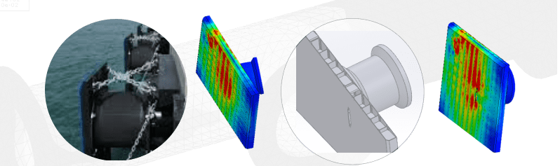
Panel de defensa de mulle (Marine fender)
High-power blower rotor
The Failure Analysis of a catastrophic failure in a high-power blower rotor allows delimiting the cause to construction and operational issues. As a verification of the validity of forbidden operating zones or bands, a 3D CAD modeling of the rotor was conducted. This includes the shaft with boundary conditions that consider the bearings’ supports with free angular alignment. Modal and stress analysis were performed due to centrifugal acceleration and pressure differentials at nominal speed.
The first calculated natural modes coincided with peaks in the vibration measurements of the repaired rotor. The stress state was within acceptable levels with a peak in the fracture initiation zone. The analysis allows predicting the sensitivity of these parameters to thickness variations in a redesign for the part’s reconstruction. It shows the critical points regarding fatigue strength and emphasizes the need for concentrated inspection of weld quality in those areas.
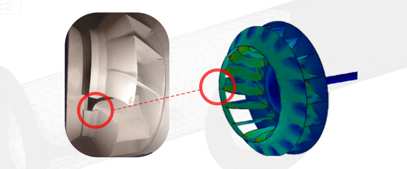
Soplador
Pump Rod
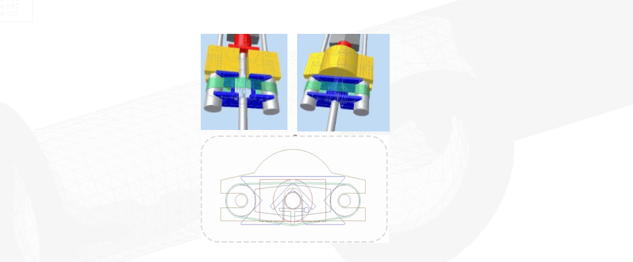
The recurrent failure of mechanical pump rods in Rotaflex-type AIB equipment led to a series of experimental analyses, FEA models, and the generation of a cause-effect tree to determine the root causes. The failure mode was identified as fatigue with a tensile-bending stress component occurring below the sling clevis.
A field inspection was conducted to determine possible factors contributing to the occurrence of the failures. Eccentricity of the sling liter with respect to the bar axis and plastic deformation found on the rods in the clamp area were detected.
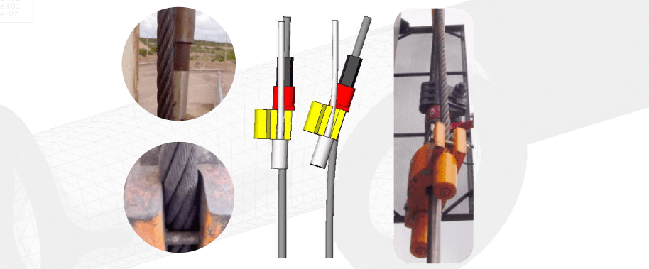
Estado de deformación obtenido del modelo 1x y 5x, A la derecha, se compara con la imagen de la barra con igual excentricidad
The FEA modeling replicates the displacement state found in the field, particularly the bar shifting at the upper end. The analysis reveals that the stress state exceeds the yield stress in the tension zone. Interestingly, compressive stresses are also observed due to the eccentricity of the load being greater than the radius of the central core by R/4. A sensitivity analysis of the stresses with respect to eccentricity can be performed.
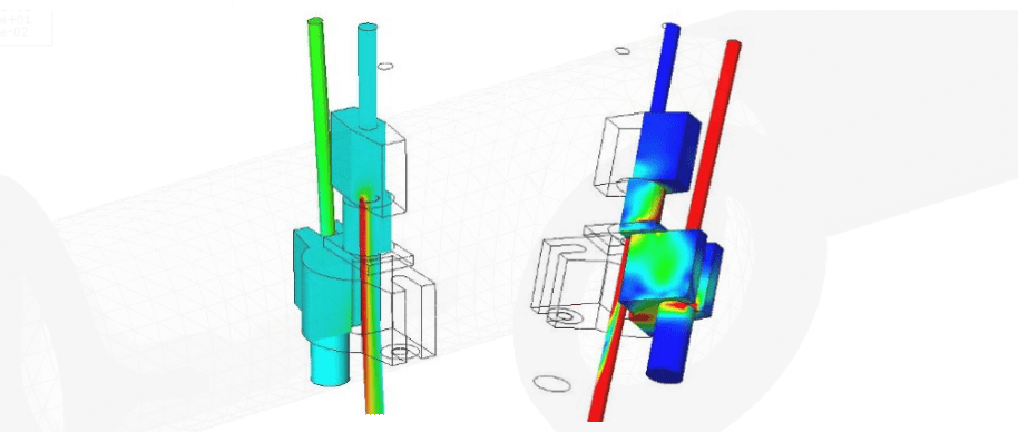
Descripción del estado tensional debido a la excentricidad del tiro de la barra
El análisis FEA de los componentes pone en evidencia la criticidad de la excentricidad en el cuelgue de la barra, lo que lleva a proponer un dispositivo centrador para eliminar el problema