In 2008, thanks to significant state support through the ANR 600 program, we set out to develop our instrumented indenter, the ESYS 10, providing the industry with a tool that allows knowing the most important mechanical properties of materials without the need for destructive testing. More than 15 years later, no more than five companies offer this service worldwide, and we are proud to be the ones providing access to this technology in Argentina and Latin America.
On this journey, we have verified the reliability and versatility of the testing machine we developed and the accuracy of the data obtained. However, in a continuous improvement process, this year we decided to experimentally verify the effect of internal pressure on the measurements. To do this, we developed a testing protocol, the results and details. It is titled «Determination of mechanical properties with ESYS 10. Effect of internal pressure and analysis of result dispersion» and we invite you to discuss the results with us in September this year.
As a preview, we can say that the results obtained allow us to affirm that the yield and tensile strength data obtained with the ESYS 10 do not depend on the stress state of the component being tested, and the dispersion of the results is within the inherent variations of the materials, being comparable to the variation of properties obtained in the same steel mill for the same material specification.
But, what is Instrumented Indentation with ESYS 10? Learn more in this article.
1. What is Instrumented Indentation with ESYS 10?
Instrumented indentation with ESYS 10 is a technique that allows determining the most relevant mechanical properties of a material by performing an indentation with a spherical ball, in several cycles, simultaneously recording load and displacement. These properties are Yield Strength (YS), Ultimate Tensile Strength (UTS), and Strain Hardening Exponent (see Fig. 1). This test is non-destructive, as it leaves only a small imprint on the material’s surface, about 0.25 mm deep (Fig. 1), and can generally be performed with the equipment in service.
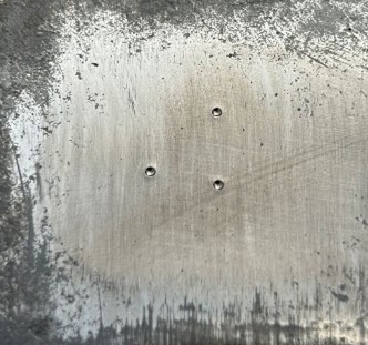
Fig. 1: Imprints on the tested material’s surface, on a surface ground with 400 grit
2. What is its utility and field of application?
Ensuring the Fitness For Service of containers, pipes, or other metallic components requires knowing their materials’ mechanical properties since allowable stresses are, broadly speaking, a percentage of the yield or tensile strength (depending on the manufacturing code).
However, often due to the transfer of assets between different owning companies, nationalizations or privatizations, or even issues such as fires or floods at documentation storage sites, companies do not always have this basic information about their equipment. This forces them to make very conservative assumptions, assuming that the materials have properties that are generally much lower than the actual ones, because to know those actual properties, they would need to extract samples and perform tensile tests (destructive), see Fig. 2. This would generate very high repair costs and lost profits, or even be impractical. The alternative is to operate the assets below their capacity to keep the risk level within acceptable margins.
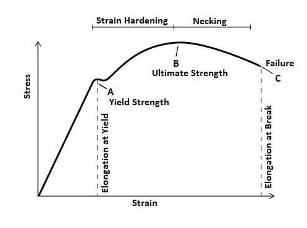
Fig. 2: Tensile stress curve.
Image Credit: https://omnexus.specialchem.com/
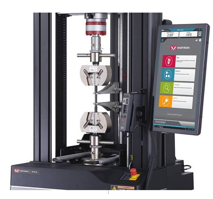
Fig. 3: Tensile test
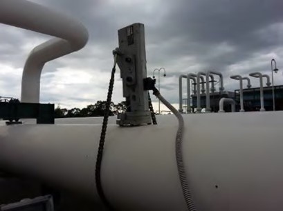
The ESYS 10 offers a superior alternative, which is to know the real properties of the material, but through a Non-Destructive Test in situ and in service, allowing then to increase service pressures and loads without increasing the level of risk (Fig. 4).
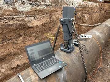
Fig. 4: ESYS 10 working in the field.
3. What is the technique based on?
The methodology is based on the work initiated by Fahmy Haggag [[i]], and continued by several researchers [[ii], [iii], [iv], [v], [vi]]. The method consists of measuring the displacement and force applied as an imprint is made on the component with a spherical tip in successively increasing load cycles.
Figure 5 shows the indentation profiles during each load and each unload, and Figure 6 shows the load-depth curve of the indentation. It can be seen that the load increases approximately linearly with the penetration depth.
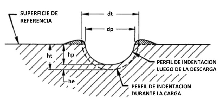
Fig. 5. Diameters and depths of indentation.
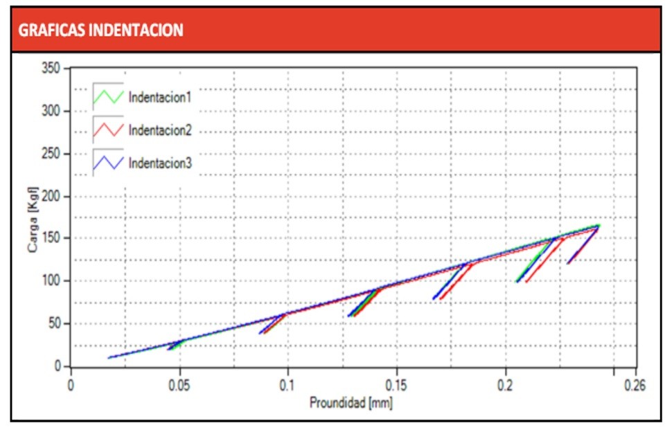
Fig. 6. Load-depth cycles of the indentation.
Unlike the uniaxial tensile test, in this case, during each load, plastic and elastic deformation phenomena develop simultaneously. Thus, for each load-unload cycle, a point of the real stress vs real strain curve of the material in the plastic region can be obtained. But how?
4. Calculation Methodology
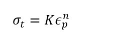
Based on semi-empirical relationships [[vii], [viii]], real plastic deformation and real stress for each cycle can be calculated as per (1) and (2):

Figure 7: Diameter of indentation and plastic deformation.
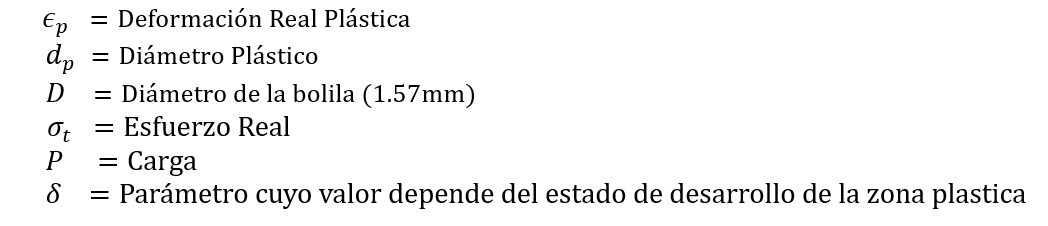
Figure 8: a) Relationship between stress and plastic deformation, b) Relationship between plastic deformation and indentation diameter.
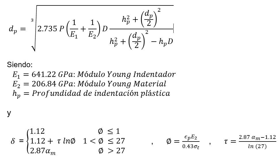
Figure 9: Calculation method of the mechanical properties of the materials.
The parameter αm must be experimentally determined from a set of material samples.
4.1 Yield Strength σy
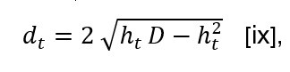
For each cycle, the total diameter is obtained from the total indentation depth as:
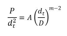
This value for each cycle, along with the measured load P, is used to obtain, through linear regression, the material parameter A and the Meyer index m, from the following equation:
Then, the material’s yield strength is obtained as:
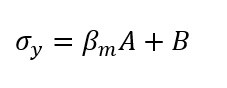
The parameters βm and B must be experimentally determined from a set of material samples.
4.2 Strain Hardening Coefficient and Exponent
The coefficient and exponent are obtained from the real strain – real stress values obtained for each indentation cycle as specified by ASTM E646 from the following relationship:
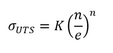
4.3 Breaking Strength
It is obtained as:
5. Equipment Description
The equipment consists of the indentation machine (Fig. 7), a control and data acquisition unit, and software specifically developed for processing on PC.
The indentation machine has a stepper motor and a reduction gearbox to allow fine control of the speed. This gearbox is linked through a clutch to a ball screw to avoid play. Through this latter mechanism, the rotary motion of the motor is converted into linear displacement, allowing the introduction of the indentation tip into the material under test.
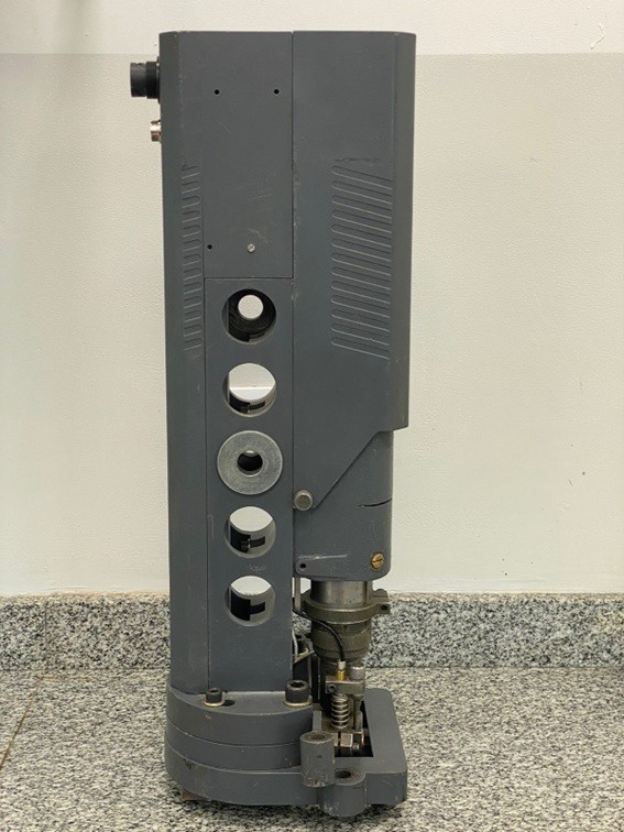
Fig. 7: Indentation machine
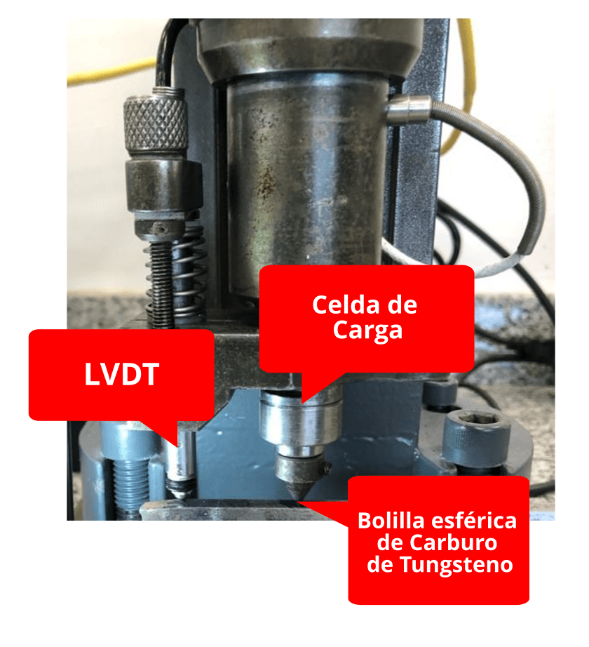
Fig. 8: Indenter components.
The indentation tip has a tungsten carbide ball with a diameter of 1.57 mm, the load cell, the load cell for load measurement, and the LVDT for displacement measurement (Fig. 8).
The control and acquisition unit is based on an industrial computer from National Instruments with motion control boards and analog data acquisition.
The readings taken are stored and then processed to obtain the various points of the stress-strain curve, from which the Yield Strength, Breaking Strength, and Strain Hardening Coefficient parameters are determined based on the methodology explained above.
6. References
[i] F.M. Haggag and K.L. Murty, «A Novel Stress-Strain Microprobe for Nondestructive Evaluation of Mechanical Properties of Materials,» Nondestructive Evaluation (NDE) and Materials Properties Ill, ed. P.K. Liaw et al. (Warrendale, PA: TMS, 1997), pp. 101-106.
[ii] «Nondestructive Detection and Assessment of Damage in Aging Aircraft Using a Novel Stress-Strain Microprobe System,» SPIE Proceedings on «Nondestructive Evaluation of Aging Aircraft, Airports, and Aerospace Hardware,» Vol. 2945, 1996, pp. 217-228.
[iii] «In-Situ Measurement of Pipeline Mechanical Properties Using Stress-Strain Microprobe – Validation of Data for Increased Confidence & Accuracy,» Pipeline Research Council International (PRCI), Report L52280e, Apr. 1, 2007.
[iv] «In-Situ Measurement of Tensile and Fracture Toughness Properties and Determination of Pipe Grade Using the Innovative ABI Test,» Gas Technology Institute Project 20568, Final Report, November 2008.
[v] “In-Situ Measurement of Tensile and Fracture Toughness Properties of Pipeline Sections Using the Innovative ABI Test of ATC’s SSM System,” Gas Technology Institute Project 20568, Addendum, February 2009.
[vi] «In-Situ ABI Testing to Determine Yield Strength, Pipe Grade, and Fracture Toughness of In-Service Oil and Gas Pipelines,» Russian Oil and Gas Technology, April 2011, pp. 22-29.
[vii] D. Tabor, The Hardness of metals, Clarendon press, Lodon, 1951.
[viii] H. A. Francis, Trans. ASME, (1976), pp. 272.
[ix] F. M. Haggag, R. K. Nanstad, J. T. Huton, D. L. Thomas, and R. L. Swain, Use of automated ball indentation testing to measure flow properties and estimate fracture toughness in metallis materials, Applications of Automation Technology to Fatigue and Fracture Testing, ASTM 1092, A. A. Braun, N. E. Ashbaugh, and F. M. Smith, Eds., American Society for Testing and Materials, Philadelphia, (1990), pp. 188-208.