INTRODUCTION
Sound waves are phenomena of mechanical vibration that propagate through different mediums, whether they are solids, liquids, or gases. These waves are related to the sounds we perceive daily with our ears, as well as the ultrasonic waves used for defect detection.
When sound waves travel through a specific medium, they do so at a determined velocity and in a predictable direction. However, when they encounter an object or a change in the medium, such as a boundary between two different materials, these waves can be reflected or transmitted according to simple rules.
This physical principle is fundamental in defect detection through ultrasonic testing. Essentially, ultrasonic waves bounce off cracks or other irregularities present in the object being examined. By monitoring the echoes generated in an area, the experienced operator can identify and locate hidden internal defects.
GENERAL DESCRIPTION OF THE TECHNIQUE
Inspecting pipelines using Guided Waves or Long-Range Ultrasonic Testing (LRUT) is a non-destructive testing (NDT) technique employed to identify the presence of material losses.
Initially designed to detect corrosion under insulation, this methodology has become a widely used tool for the rapid detection of corrosion in pipelines with a wide inspection area.
Unlike conventional ultrasonic testing, which focuses on specific areas, the guided wave system uses a ring of transducers to generate low-frequency ultrasonic waves that propagate in both directions along the pipeline. This allows inspecting long sections of the pipeline from a single point of application.
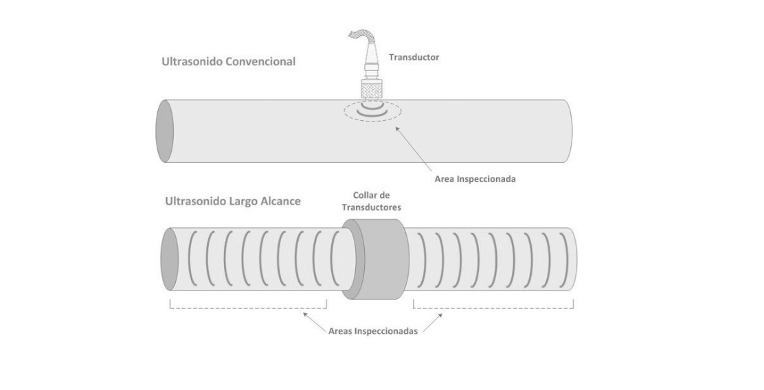
Non-Destructive Testing (NDT) using Ultrasonics enables the rapid detection of defects without the need to take the duct out of service, reducing access and inspection costs by limiting the removal/replacement of insulating or coating material to only the section where the transducer ring is placed.
FUNDAMENTALS OF LONG-RANGE ULTRASONICS
Trials using ultrasound (UT) are extensively used as a non-destructive testing (NDT) technique to detect defects in a wide variety of structures and components, both during their manufacturing stage and while in service.
Conventional Ultrasonography employs ultrasound waves in the MHz range. The pulses travel in a narrow beam, and the echoes from defects located within this beam are then detected, allowing for defect characterization. The inspection range of this method is generally measured in millimeters or centimeters.
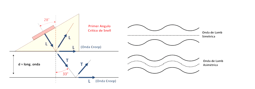
Long-Range Ultrasonography (LRUT) is based on the generation of plate waves or Lamb waves. These waves, with frequencies in the KHz range, propagate according to the interaction of surface waves generated by reflections (at a specific angle of incidence) of an ultrasonic beam on the faces of a thin plate.
These waves propagate several meters through the material thickness and can be either asymmetric (in-phase surface waves) or symmetric (out-of-phase surface waves).
The ultrasonic waves of the guided wave method can be considered a particular case of Plate Waves or Lamb Waves, traveling through a waveguide, typically a pipeline, instead of a thin plate.
PRINCIPLE OF DETECTION
The ultrasonic guided waves that can be generated in a pipeline are classified according to their symmetry with respect to the axis of the pipe into:
Symmetric Waves: Longitudinal Mode or Mode
Asymmetric Waves: Mode
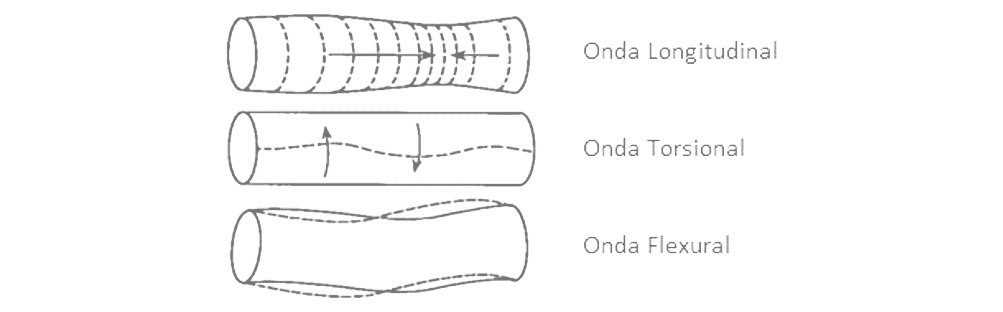
By using several rings of piezoelectric transducers, it is possible to generate symmetric guided waves (longitudinal or torsional, depending on the arrangement of the transducers) that propagate in both directions of the pipeline.
The mechanism of detecting discontinuities is based on the fact that the propagation of these waves is determined by the frequency of the wave and the cross-sectional area of the pipeline.
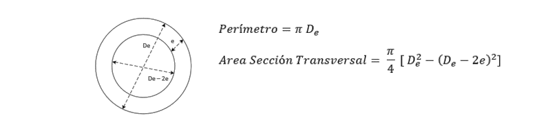
At points where the wave encounters a change in the cross-sectional area of the duct, whether it increases or decreases, a percentage of the energy reflects and returns to the transducers.
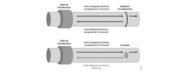
In the case of events like a circumferential weld on the duct, the increase in thickness is symmetrical around the entire duct. As a result, the wave will advance from a uniform reflector, generating a reflected wave that is also symmetrical with the same mode (longitudinal or torsional) as the incident wave.
In the case of a corroded area, the loss of thickness will be localized, causing scattering of the incident wave and leading to a mode conversion of the reflected wave, changing it to an asymmetric (flexural) mode.
By using transducer rings capable of recognizing these asymmetric reflections and employing non-dispersive propagation modes and frequencies, it is possible to determine the location of the discontinuity on the duct based on the time at which the reflected wave is received.
Furthermore, considering that pipe welds reflect about 20% of the incident signal, it is possible to estimate the loss or increase in material in the cross-sectional area of the detected indications.
The methodology is characterized by:
- Being capable of detecting metal loss from 3% of the cross-sectional area.
- Providing reliable detection for metal losses from 9% of the cross-sectional area.
Certain existing technologies, like Teletest Focus+, additionally allow the creation of «focus» on the detected indications, enabling the determination of the concentration and circumferential position of the thickness loss.
DESCRIPTION OF THE EQUIPMENT
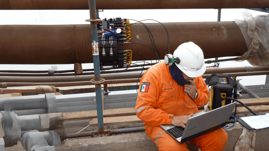
The Teletest Focus+ system consists of three main components: the set of inflatable collars for different pipe diameters with the required number of modules and piezoelectric transducers in each case, the Teletest Multimode Pulsar/Receiver unit, and a notebook with the Teletest WaveScan analysis software.
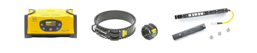
The inflatable collars are made from a single piece of carbon fiber reinforced with Kevlar, along with straps for handling and a quick metal fastening system to facilitate their assembly onto the inspected duct. The size of the collars is adjusted according to the duct diameter.
Inside the collars, modules with piezoelectric transducers are attached. The quantity and type of modules used depend on the collar diameter, employing between 8 and 16 «mini» modules for diameters from 2″ to 4″ and between 24 to 56 «multimode» modules for diameters from 6″ to 24″.
As low-frequency transducers, they do not require coupling gel, and the pressure exerted by the inflated collar alone is sufficient for the effective transmission of ultrasonic waves to the duct.
The unit, completely controlled from the WaveScan software, generates the excitation required for the transducers to produce the injected ultrasonic wave modes into the duct and collects the received echoes. The unit also controls the air pressure in the collar throughout the entire test duration.
The software allows for controlling the unit, along with data collection and processing, visualization, and analysis in an A-scan format, storage of results, and report generation.
Additionally, WaveScan enables the creation of «focus» on indications and the A-Map function that provides a circumferential distribution of indications on the pipe.
EVALUATION AND PRIORITIZATION OF INDICATIONS
The test results correspond to the amplitude of the received reflections for each tested frequency. On the screen, symmetrical reflections (black curve) and asymmetrical reflections (red and blue curves) are observed.
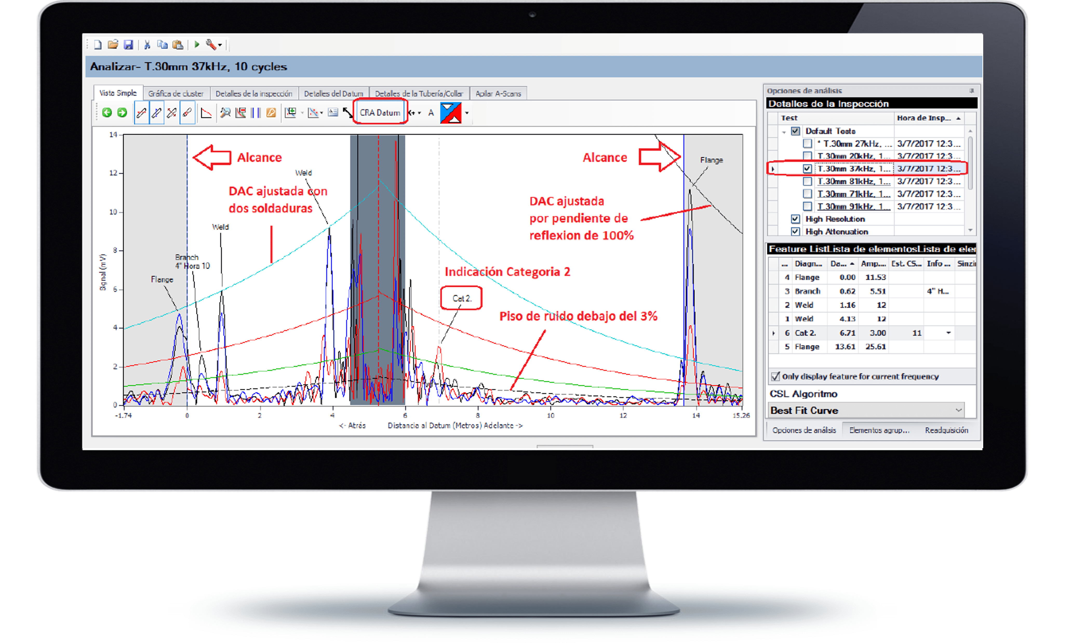
The equipment’s DAC curve is calibrated according to the amplitude of the received symmetrical reflections from the welds (light blue DAC curve, typically 20% of the injected signal).
Asymmetrical reflections that cannot be identified as being caused by a pipe feature (contact with support, bypass, etc.) are categorized based on the reflection amplitude as follows:
• Category 1: Reflections less than 9% (Green DAC curve).
• Category 2: Reflections less than 14% (Red DAC curve).
• Category 3: Reflections greater than 14% (Red DAC curve).
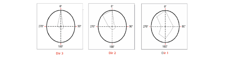
For each indication, a focus test is performed, indicating how concentrated the area loss is at a circumferential position of the pipe. The result of the focus test is categorized into Dir1, Dir2, and Dir3.
All the indications obtained through the guided wave methodology must be located and evaluated with a direct method, either using comparators for external defects or conventional ultrasound for internal defects.
The categorization by amplitude and directionality of each indication allows the construction of a severity matrix of the indications, which helps prioritize their evaluation.

INSPECTION CHARACTERISTICS
- Applicable in diameters from 2″ to 24″ (Consult for other diameters).
- 100% coverage of the section.
- Testing range:
- Typical Aerial: +/- 40m.
- Typical Buried: +/- 15m.
- Ideal Conditions: +/- 150m.
- Productivity: Normally 8 to 12 tests per day. or
- Typical Aerial: 800 m/day.
- Typical Buried: 300 m/day.
- Ideal Conditions: 3000 m/day.
- Service at temperatures from -30°C to 125°C.
- Detection of both internal and external metal loss.
- Sensitivity:
- Metal loss from 3% of the wall cross-sectional area.
- Reliable detection of indications of 9% metal loss and above.
- Discrimination between detected indications and pipe features: welds, changes in direction, supports, branches, etc.
- Longitudinal accuracy of approximately +/- 100 mm.