It is well known by those responsible for asset management in industrial facilities that systems composed of what is generically known as small bore piping and connections represent a significant threat and a particular challenge to the integrity due to their recurring failure frequency. So much so that the well-known saying «Small bore, big problem» has been coined.
Although the terms «small bore piping» and «small bore connections» refer to the conditions that are the source of these problems, these terms have different definitions within standards.
Small bore piping (SBP, Small Bore Piping) is defined, for example, by API 570, Piping Inspection Code, as pipes and fittings with a diameter less than or equal to NPS 2, matching with the IOGP’s Specification S-716, which includes pipes up to 50 mm or 2 inches.
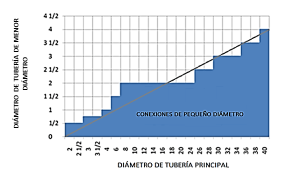
On the other hand, small bore connections (SBC, Small Bore Connection) are defined based on the diameter ratio of the pipes involved. An SBC is defined as a connection between an NPS 2” (DN 50) or smaller pipe to one of a larger diameter, including connections where the diameter ratio between the secondary pipe (Ds) and the primary pipe (Dp) is less than 10% ( Ds/Dp < 0.1) (Fig. 1).

Fig.1: Ratio between diameters defining SBP Situations
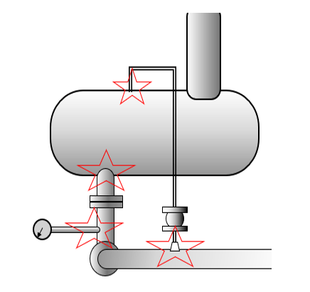
If the ratio Ds/Dp > 0.25, the connection is not considered SBC, regardless of the smaller pipe’s diameter. The concept of «larger diameter piping» could also describe equipment like reactors or exchangers connected to the SBC (Fig. 2).

Fig. 2: SBP situations, critical points under mechanical stress and fatigue
SBP, due to their dimensions (slenderness) and mass distributions (valves, meters, heavy transmitters compared to the piping), are prone to vibration-related problems and generally fail due to fatigue. This is because their slenderness or mass distribution makes them susceptible to resonating, excited by vibrations from the main pipe, which may even be considered acceptable. These vibrations can amplify in the SBP by several dozen times in amplitude.
The most critical points are the SBCs, as these produce geometric discontinuities and abrupt thickness variations at welds and threaded or flanged joints.
Two factors contribute to increased SBC failures: one is the implementation of variable speed drives in motors, which alters the resonance conditions initially predicted; the other is the advantageous implementation of remote control and monitoring systems, which facilitate and optimize operations but require more information and, consequently, more sensors and SBP.
In recent cases, SBC failures have been responsible for pipeline and production facility shutdowns lasting weeks. The costs associated with this type of failure are more related to the downtime than the direct repair cost, but the risk potential can be very high.
Risk control associated with this type of failure should be considered throughout the asset’s lifecycle. From the design stage, all possible sources of disturbances such as pulsations, transient events, turbulence, reciprocating machine excitations, acoustic resonances, among others, should be evaluated.

Fig. 3: Fatigue resistance assessment in SBP joints. Failure mode analysis, RX inspection, and stress analysis
These factors should determine the detailed design of SBPs with specific consideration for fatigue resistance (Fig. 3). During commissioning and operation, all critical points must be monitored, especially during transients and events like purging, venting, and flushing of pipes.
Another threat to small bore piping arises when used for control and product dosing in high-pressure processes. In these cases, pumps are of the reciprocating or gear type. As the pressures used are logically higher than those of the processes and these systems also generate pulsations in the fluid, conditions are created that can lead to internal pressure failure. In this case, failure will also be due to fatigue.


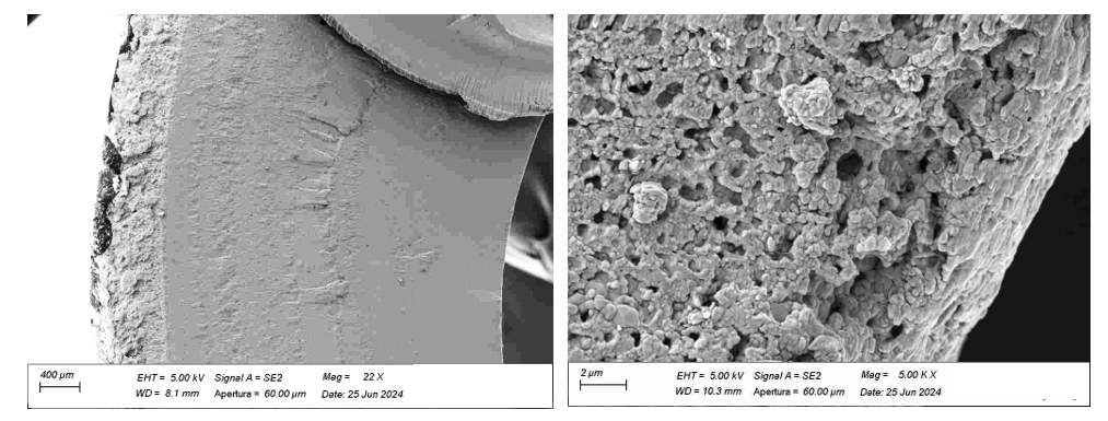
Fig. 5: Fatigue failure in CPVC SBP due to excessive porosity generated in the chlorination process
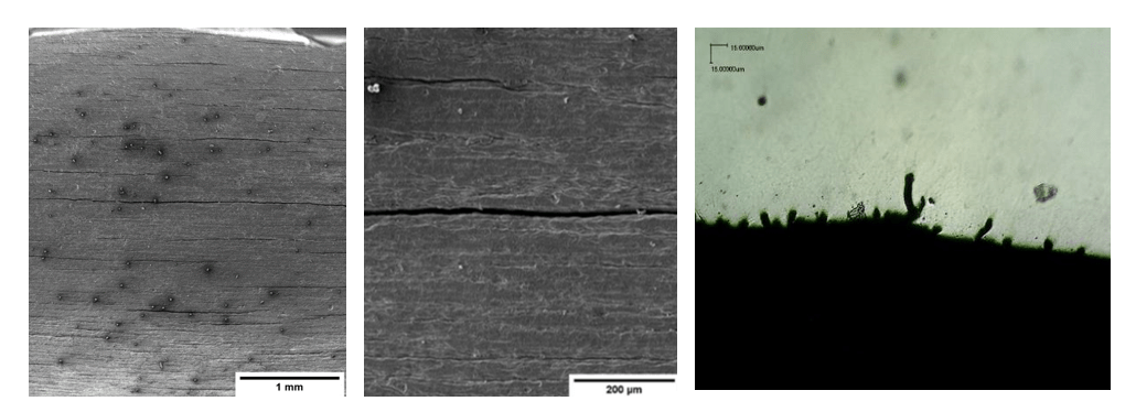
Small diameter tubes for high pressures are produced using various techniques, such as extrusion and subsequent diameter calibration by stretching, either hot or cold. The material undergoes large deformations, which can create roughness or longitudinal cracks that promote fatigue failure. Similarly, in polymer tubes, the manufacturing process can create discontinuities in the material (Fig. 4 and 5). Quality control of different batches of small diameter tubes must be carried out through metallographic and microscopic inspection.


