When talking about numerical modeling in the field of science and engineering, reference is being made to techniques that use mathematical models to represent phenomena for which there is a more or less adequate description based on theories and observations accepted as valid.
These mathematical models are expressed in equations or systems of equations. Generally, differential equations whose solution provides us with a description of the studied phenomenon. These solutions must be consistent with the observations for the mathematical tool to be useful, that is, it can be used with a reasonable degree of reliability to predict results.
The resolution of these differential equation systems analytically is almost impossible, so it is necessary to resort to computers, which is generally referred to as numerical resolution or calculation.

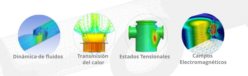
In engineering and industry, the phenomena of interest to model are as diverse as those related to fluid dynamics, heat transfer, material stress states, electromagnetic fields, etc. Currently, it is possible to link phenomena of different nature in the so-called Multiphysics analysis.
Finite Element Modeling
There are various ways to implement numerical modeling so that the model adjusts to the phenomenon being studied as necessary, and the results are reliable and applicable. In particular, the technique of modeling through Finite Elements has grown rapidly in recent years and has become an essential tool in engineering, driven by the overwhelming increase in processor power and software offerings. This is why numerical modeling has converged in practicality in the use of Finite Elements, referring to the technique as FEA (Finite Element Analysis), FEM (Finite Element Method) that some prefer to call FEM (Finite Element Method) to differentiate the methodology from the implementation, a distinction that is unnecessary in engineering since everything converges on the use of commercial software that packages all the necessary tools to carry out this type of analysis.
This can lead to the interpretation that FEA is simply an accessory to CAD packages, and the associated risk is that its use without a solid knowledge base of the phenomena being modeled, as well as the underlying principles in the method, can lead to errors or gross inaccuracies.
Phases of the Implementation of an Analysis through FEA (Finite Element Analysis)
The implementation of an analysis through FEA (as we will call it) involves a series of necessary instances, each of which must be adequately completed and to an appropriate extent. Most commercial programs currently offer remarkable practicality, highly intuitive interfaces, and contextual guides that collaborate throughout the process.
In general, an analysis consists of three phases: (1) preprocessing, where the analyst creates a 3D CAD model, generates a finite element mesh, and applies certain parameters and boundary conditions to the model, (2) Solution, where the program solves the equation systems, and (3) post-processing, where the result is evaluated and presented in various ways for subsequent interpretation.

The analysis sequence begins with the generation of a CAD model, usually 3D, of the element(s) involved in the analysis. When FEA is used in Design, the CAD model is an essential part of the process and is typically modified until the final product is obtained. On the other hand, when the model is used as a tool in projects such as Failure Analysis, Fitness for Service, Equipment Requalification, etc., the geometry must be properly surveyed.
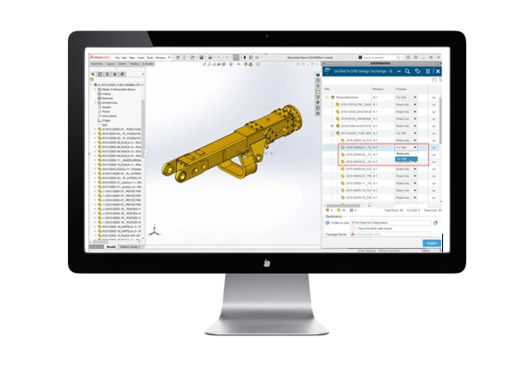
Example of CAD model using Solidworks software
Here comes a very important factor that can simplify or, on the contrary, make the rest of the process extremely costly, even computationally unfeasible. At this stage, it is necessary to have a clear objective of the analysis to be carried out, and criteria regarding the relevance of the details of the parts that must be included or removed in the CAD model must be applied. For example, it is useless to include the thread at the end of a shaft when trying to define the stress state in a keyway at the other end, or to include a purge nipple in a duct when evaluating thickness loss 300 m away from it.
As much or more criterion and experience is necessary for the following stages, not so much in the selection of the properties (of all types) of the materials, since they are usually offered in adequate libraries along with the software package, but in the so-called boundary conditions of the problem, that is, the restrictions or links, as well as the system of loads to be considered.

In the restrictions (the way the part is supported or held and its contact relationship with other parts), small differences in the criteria for interpreting the real conditions can generate large differences in the results, especially when deformation coupled to other deformations such as thermal or Poisson effects are inadvertently restricted or when symmetry conditions are abused.
The load system imposed on the part model usually has greater uncertainty. These external requests can be implemented as point loads, pressures, inertia loads due to accelerations, contact stresses with other parts, loads introduced by the medium such as hydraulic loads, waves, wind, snow, etc. In the vast majority of cases, their determination must be based on the calculation according to current regulations or sources that provide statistical and worst-case scenario information, such as storms, earthquakes, precipitation intensity, etc.
The meshing of the model deserves special consideration, as it is the part of the process where the model is discretized and where the analyst has more freedom of action. Meshing is a key stage in obtaining results with adequate precision. Generally, the smaller the mesh size, the more accurate the solution will be. The downside is that the more precision you seek, the longer resolution times are extended due to the size of simulations in terms of the number of elements and degrees of freedom.
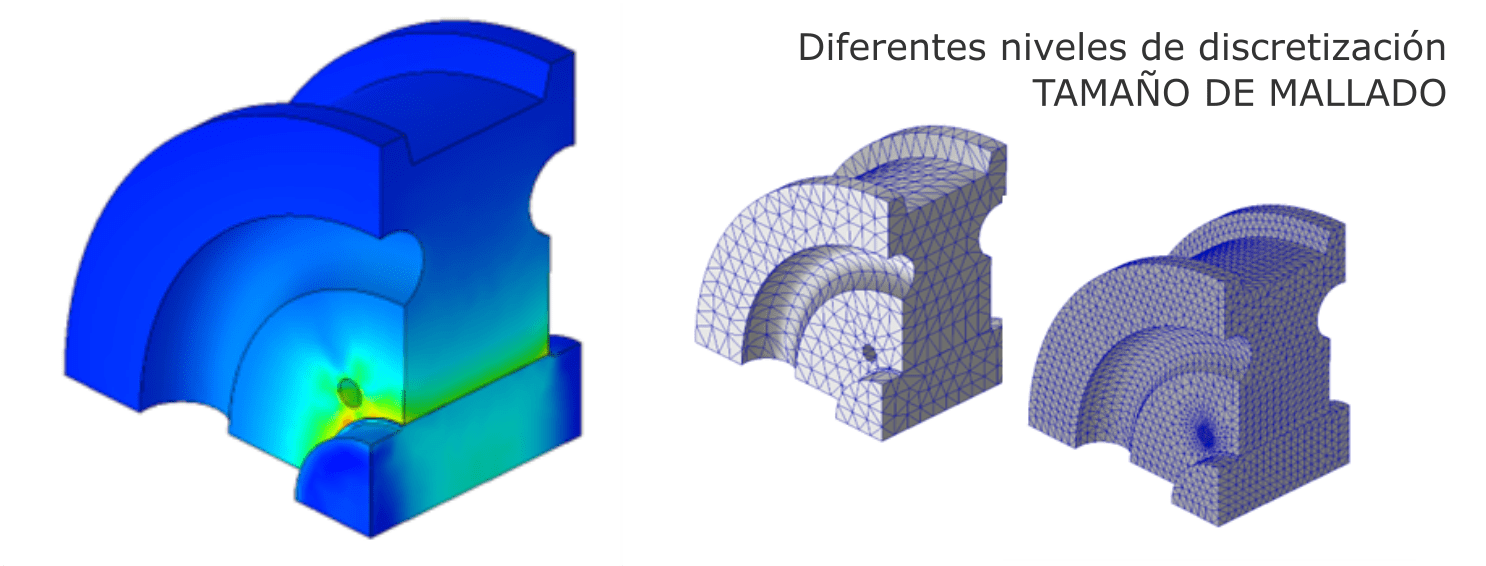
To obtain the optimal balance between precision and resolution time, it is advisable to carry out convergence studies, that is, to vary the mesh size and study the effect on the results. It makes no sense to spend additional hours running a simulation with a dense mesh if a coarser mesh will give you the results you need.
Somehow, modeling involves knowing the result before obtaining it. Therefore, unless you have experience, you don’t know where to refine the mesh» Dr. Ivatury Raju, NASA
Results Presentation
Finally, having obtained the solution of the modeling, the presentation of the results is completely linked to the initial objective. Thus, depending on the type of analysis, values of stress or strain distribution, or velocities and pressures in the case of fluids, for example, are obtained.
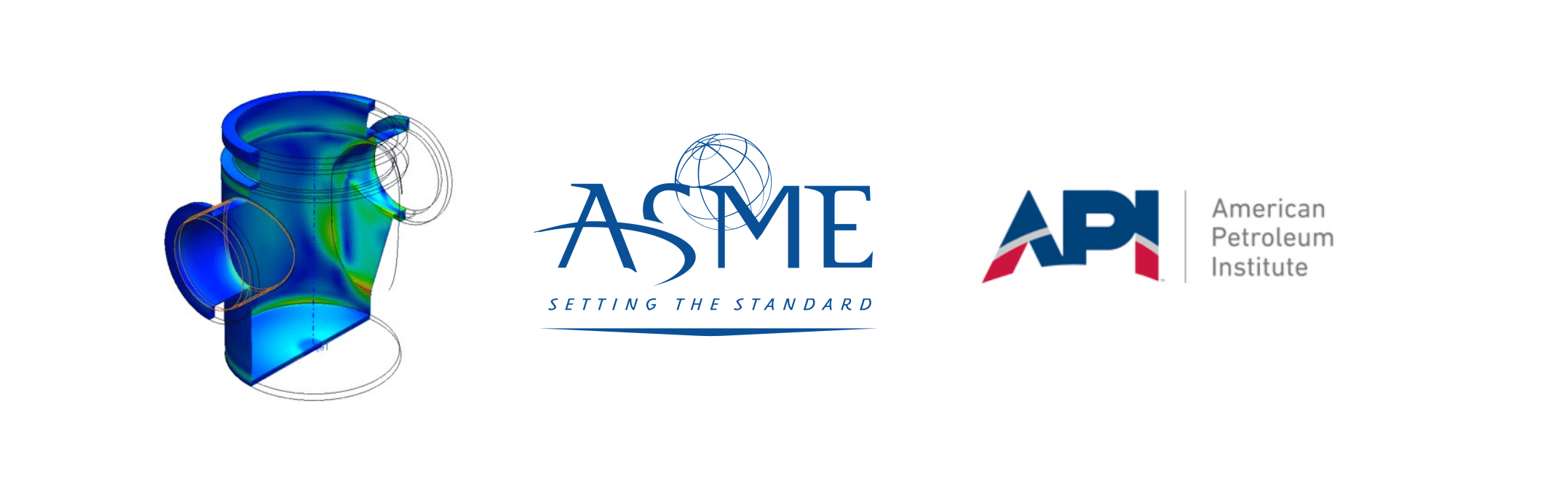
The analysis of the results finally passes through the acceptability criteria of said results according to the application norms. In general, such norms revolve around the concept of principal stresses, yield criteria, and rupture hypotheses. Paradoxically, although numerical modeling provides complete information regarding the stress state, validation by means of application norms such as ASME BPVC (Sec. VIII Div. 2) and API RP 579 involve a normalization of the stress state in terms of, for example, membrane stresses, bending stresses, and peak stresses separating them into primary and secondary ones. The norms also provide the acceptability criteria for each category. The norms provide verification and design criteria based on the convergence of elastoplastic modeling, that is, the determination of the limit where structures globally collapse due to plasticity.
Results Verification
The most important stage of numerical modeling is perhaps the least referenced in application manuals and courses and is that which depends mainly on the experience of the analyst. This stage of verifying the results by other “independent” means. At different stages of modeling, there is the possibility of introducing errors or incorrect criteria, and the analyst must verify whether the modeling responds to the user’s intentions or if, for various reasons, the results do not appear reasonable.
Some experience-based techniques are often used at this stage.

Verify «roughly» tensions by manual calculation
This is almost always possible, at least for some parts of the model where the geometry and loads present a friendly situation for the calculator. The results of the model cannot be far from what is calculated.

Observe the deformation of the model
The experienced analyst «knows» how the deformation of the structure or part being modeled should look. The most errors are detected by observing unexpected behaviors of the model, mainly from contact conditions and constraints.

Verify the reactions of the constraints
In an equilibrium model, the reactions and applied loads must compensate each other. This verification highlights errors in the solver’s output. Programs often warn of errors during execution that could have been overlooked.

Check if the reported maximum stresses are real or come from singularities introduced in the CAD model or through constraints
Knowing how to eliminate such singularities or simply when to ignore them is part of the analyst’s expertise.
In the next installment, we will see concrete applications in Failure Analysis projects, complemented by some examples from our experience.